Check back regularly or subscribe for updates. Email us at jandkaudiodesign@gmail.com, or fill in the form on the left.

Saturday, December 28, 2013

Transformer Measurement


Transformer Measurement

Transformer measurement is very similar to inductor measurement but with additional parameters to measure due to the secondary winding being present. Below is a representation of a transformer with all the parameters involved in the measurement.

  • L1 = Primary Inductance
  • L2 = Secondary Inductance
  • C1, C2 = Distributed capacitance of windings
  • R1, R2 = DC resistance of windings
  • C = Inter-winding capacitance
  • M = Mutual inductance

L1 and L2 can be measured directly using LCR. When measuring L1, L2 should be left open, and vice versa. Leakage inductance (self-inductance due to <100% coupling of transformer windings) can be measured with L2 is shorted.

C can be measured by measuring capacitance of 1 point of input at primary winding and 1 point of input at secondary winding (of same phase).
Turns ration (N) can be measured by connecting a resistor to the secondary. From the impedance measured from the primary, one can deduce the turns ratio with this formula:
Z = N2R
N = sqrt (Z/R)

That’s about it for basic transformer measurement.

J&K Audio Design
29/12/2013


Product Lists  

Level 0

Level 3: depends on type, size and complexity. Email us for details.
Iso-trans: link 1, link 2
* Finished amplifiers, DACs, audio gadgets, upgrades and repairs - this is not our core business and we do it out of passion. We do not have fixed models, fixed price and we customize for each individuals. The sky is limit of creativity.  
* Our product lines are always improving and increasing. If you do not see what you want, contact us!  
* Please email for volume discounts, distributor and OEM pricing.

Inductor Measurement


Inductor Measurement

Frequency dependency is common to all real-world components because of the existence of parasitics.
Not all parasitics affect the measurement, but some prominent parasitics determine the component’s frequency characteristics.

For inductors, parasitic capacitance causes a typical frequency response behavioral change. Due to the parasitic capacitance (Cp), the inductor has a maximum impedance point at the SRF (where wL = 1/(wCp).) In the low frequency region below the SRF, the reactance is inductive. After the resonant frequency, the capacitive reactance due to the parasitic capacitance is dominant. The SRF determines the maximum usable frequency of capacitors and inductors.

DC bias dependency is very common in semiconductor components such as diodes and transistors. In the case of cored-inductors, the inductance varies according to the DC bias current flowing through the coil. This is due to the magnetic flux saturation characteristics of the core material. Inductors are conductive at DC. Often a DC current dependency of inductance needs to be measured. 

J&K Audio Design
29/12/2013

Product Lists  

Level 0

Level 3: depends on type, size and complexity. Email us for details.
Iso-trans: link 1, link 2
* Finished amplifiers, DACs, audio gadgets, upgrades and repairs - this is not our core business and we do it out of passion. We do not have fixed models, fixed price and we customize for each individuals. The sky is limit of creativity.  
* Our product lines are always improving and increasing. If you do not see what you want, contact us!  
* Please email for volume discounts, distributor and OEM pricing.

Friday, December 27, 2013

Testing Chokes


Testing chokes and transformers are easy. One just have to connect them to an LCR meter, that it, right? RIGHT??? Well, it’s not entirely correct. It is only partially correct.

Take power supply choke for example, a certain DC + AC current will pass through the choke and the inductance will change due. When the core is saturated, the inductance will drop drastically and therefore the measurement of the choke with respect to the DC current will be required. On top of that, the operation frequency is also needed to be considered where some chokes will be built to work for 50-60Hz, 100-120Hz, 440Hz or even more if it is for plate or anode & grid loading. 

This will ensure it meets the requirement when it is loaded at the intended operating DC current. The design of the choke / transformer must ensure that there are enough flux density margins to avoid saturation the intended DC + AC being applied. If it saturates, it is as good as not having an inductor on the circuit and affect the results – high power supply ripple / noise and etc. 

Measured inductance is only correct under intended DC load conditions.

So, it is crucial to test the chokes and transformer at realistic or intended DC load conditions. Below is a very typical setup for measuring inductor. If the LCR meter / LCR analyzer is capable of biasing the measured component, the you can measure the inductor at the desire DC bias.
If your LCR meter is incapable of providing DC bias, then another method is required – providing external DC bias current to complement the LCR meter, as follow:
An external DC power supply – connecting it to the current output, will provide the desired DC bias to the choke / transformer for accurate inductance measurement. There is a problem with this setup. Conventional power supply will usually have large output capacitance and this will affect the inductive impedance of the device under test – choke and cause measurement error.
To overcome this measurement issue, one can add a relatively large (compared to DUT) inductor in series with the DC power supply to isolate the DUT from the DC power supply. The series inductor will have to be very large in order provide better accuracy to the measured value. 

Another way of doing it would be to use a DC power supply with a constant current output stage that has high impedance to isolate the DC supply from the DUT. This enables the DUT to be tested easily. There are some readily available DC supplies in the market but they are not cheap. 

One suggestion that we got from our readers is that one can build the DC supply themselves – using the 3-pin regulator IC - LM317 and the likes in constant current mode. Voltage mode will not work as there will be capacitors at the LM317 output. 

We’ve NOT tried so since Hameg 8118 has the DC bias function for up to 200mA of DC current and it is NOT proven to work. Some other LCR analyzer has external DC bias option where one can connect an external DC bias directly to the LCR analyzer for such functions. 

If you’ve done so, please let us know if it works. Our readers would be interested to see if this suggestion works.

Note: External current bias protection circuit might be required, depending on the LCR analyzer used. 


J&K Audio Design
28/12/2013

Product Lists  

Level 0

Level 3: depends on type, size and complexity. Email us for details.
Iso-trans: link 1, link 2
* Finished amplifiers, DACs, audio gadgets, upgrades and repairs - this is not our core business and we do it out of passion. We do not have fixed models, fixed price and we customize for each individuals. The sky is limit of creativity.  
* Our product lines are always improving and increasing. If you do not see what you want, contact us!  
* Please email for volume discounts, distributor and OEM pricing.

audioXpress Magazine

Dear readers,

Courtesy of audioXpress, we get to post this on our website. It's a short interview of Ken in audioXpress magazine.

audioXpress has been serving up the best in DIY audio for more than a decade! With an increased focus on professional audio, acoustics, and audio electronics, audioXpress is expanding its coverage and content to better serve audiophiles worldwide.

Enjoy!


J&K Audio Design
28/12/2013

Click here to return to latest publication.


Winding Transformer


Winding Transformer

We found these interesting video on Youtube about winding transformer that I'd like to share with you all.

Although the methodology used is not according to our standards and practices, definitely it is something to begin with and will be useful for crude transformer building. If you follow our blog, you would have discovered that winding a good transformer actually covers more ground that this video.

Enjoy:


On a side note, if you'd like to test or prove that you understand or know more than the video composer, do post in the comments section what is done right and what is done wrong. We shall see how good you are at transformer design.

J&K Audio Design
27/12/2013

Product Lists  

Level 0

Level 3: depends on type, size and complexity. Email us for details.
Iso-trans: link 1, link 2
* Finished amplifiers, DACs, audio gadgets, upgrades and repairs - this is not our core business and we do it out of passion. We do not have fixed models, fixed price and we customize for each individuals. The sky is limit of creativity.  
* Our product lines are always improving and increasing. If you do not see what you want, contact us!  
* Please email for volume discounts, distributor and OEM pricing.


Power Supply Design Guide

Power Supply Design Guide

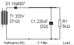
The type of rectification and filter topology will determine the output voltage and current. You can use the following guide to determine the voltage you need at the input and output of the transformer for your design or when you order your transformers.

Assumptions:

  • V.AC is in RMS.
  • RMS ripple current in filter capacitor is >2-3x the DC load current.
  • Diode voltage drop is not included.
  • Diode requirement
    • Full wave, per diode average current is 0.5 of I.dc.
    • Half waive, per diode average current is 1.0 of I.dc.
    • 2x the current amount is recommended to take turn-on surge into consideration. 
    • Full wave, reverse voltage rating is >=1.4 x V.AC.
    • Half wave, reverse voltage rating is >=2.8 x V.AC.

Half Wave Capacitor Input
  • Vdc = 1.41 x Secondary V.AC
  • Idc = 0.28 x Seconday I.AC


Full Wave Capacitor Input (V.AC = total of center-tap winding)
  • Vdc = 0.71 x Secondary V.AC
  • Idc = 1.00 x Secondary I.AC


Full Wave Choke Input (V.AC = total of center-tap winding)
  • Vdc = 0.45 x Secondary V.AC
  • Idc = 1.54 x Secondary I.AC


Full Wave Bridge Capacitor Input
  • Vdc = 1.41 x Secondary V.AC
  • Idc = 0.62 x Secondary I.AC


Full Wave Bridge Choke Input
  • Vdc = 0.9 x Secondary V.AC
  • Idc = 0.94 x Secondary I.AC


Now you know what capacity to get when you order your transformers! Don't spend unnecessary money on over-sized transformer that does not good but harm sometimes due to over-voltage!


J&K Audio Design
27/12/2013

Product Lists  

Level 0

Level 3: depends on type, size and complexity. Email us for details.
Iso-trans: link 1, link 2
* Finished amplifiers, DACs, audio gadgets, upgrades and repairs - this is not our core business and we do it out of passion. We do not have fixed models, fixed price and we customize for each individuals. The sky is limit of creativity.  
* Our product lines are always improving and increasing. If you do not see what you want, contact us!  
* Please email for volume discounts, distributor and OEM pricing.


Search This Blog

Product Lists

Product Lists

Level 0: link 1

Level 1: link 1, link 2, link 3, link 4

Level 2: link 1, link 2, link 3, link 4, link 5, link 6, link 7, Link 8, link 9

Level 3: depends on type, size and complexity. Email us for details.

Iso-trans: link 1, link 2

Power-trans: link 1

* Finished amplifiers, DACs, audio gadgets, upgrades and repairs - this is not our core business and we do it out of passion. We do not have fixed models, fixed price and we customize for each individuals. The sky is limit of creativity.

* Our product lines are always improving and increasing. If you do not see what you want, contact us!

* Please email for volume discounts, distributor and OEM pricing.